
'Light at the End of the Tunnel' - light from tunnel
Here is an example shot at Clear Angle Studios using cross polarised light, (left) polarised light (middle), and what happens when we subtract one from the other, which reveals the spec (of which I have desaturated).
Maximummagnification cameralens
Macro lenses are specifically designed to deliver optimum optical performance at very short focusing distances and will usually be sharpest at close range, but that doesn’t mean that you can only use them for macro photography. Many macro lenses are also capable of excellent performance when shooting normal subjects at normal distances as well.
Advanced Control Solutions offers manufacturers in Georgia and Tennessee a comprehensive selection of automation products and services.
And here is an example of a prop shot under cross polarised and polarised light, and then the subtraction (and desaturation) process.
Circular polarising filters (CPF) are made of special materials that are able to block one of the two planes of vibrations depending on how you rotate the filter. Do note, however, that by using a CPF, you will be reducing the amount of light transmission, and therefore, you will need to shoot a Macbeth chart with and without the CPF. This will allow you to properly grade your cross-polarised images later on for texture projection.
Do note, however, that by using filters on the lights and the lens, you’ll be reducing the amount of light transmission. Therefore, you’ll want to double-check your exposure as you shoot and make sure to shoot the Macbeth chart for each of the setups (unpolarised, polarised and cross-polarised). This will allow you to grade and expose your images later on.
Shooting under cross-polarised light is extremely useful for texture artist and a fantastic way to gain a truer reference of the surface colour and the type of material itself. For metallic materials for example, we’ll just be left with black as true metals do not have any diffuse colour. So not only is it a great way to find the diffuse colour of non-metals but also a great way of figuring out what is a metallic object and what is non-metal.
Maximummagnificationformula
Here at CAVE Academy the beauty of giving and sharing is very close to our hearts. With that spirit, we gladly provide Masterclasses, Dailies, the Wiki, and many high-quality assets free of charge. To enable the team to create and release more free content, you can support us here: Support CAVE Academy
This will not be an in-depth walkthrough of setting up a look dev and texture shoot, but below, you’ll be able to watch a short timelapse video of how I go about setting up a shoot (although this is generally configured depending on the type of asset I am shooting).
To capture cross-polarised shots, we’ll need to cover all the light sources with linear polarising filters. If you are using multiple lights, the polarising filter must be going in the same direction (for example, vertical). You DO NOT want one light to have a filter running horizontally and another light to have a filter running vertically. If you then apply a circular polarising filter (CPF) onto your camera lens, and then rotate the CPF to be perpendicular (in this example, horizontal) to the light filters, you should then be able to remove all the highlights and the glare, and be left with wondrous colour. Easy peasy.
Reveal both personal and business contact details, including emails and phone numbers, and close your most valuable buyers. Sign Up for Free
[1] Minimum focusing distance (approx. 13 cm / 5.1 in. at 1x magnification) [2] Working distance (approx. 2 cm / 0.8 in. at 1x magninfication) [3] Minimum focusing distance (approx. 35 cm / 13.8 in. at 1x magnification) [4] Working distance (approx. 16 cm / 6.3 in. at 1x magnification) [5] Image sensor plane
There are many ways in which unpolarised light can be polarised. For example, through reflection, refraction and scattering but for now, we’ll stick to using a filter.
Another important characteristic of macro lenses used at short range is that they have very narrow depth of field. That means they have to be focused very carefully to get the desired details in perfect focus. A tripod can make focusing easier in some situations. You might have to stop the aperture down quite a bit to achieve sufficient depth of field with some subjects. But shallow depth of field can be an advantage, emphasising the essential in-focus detail while defocusing and de-emphasising distracting background.
When done correctly, cross-polarised light can strip out all the reflection and the result can then be graded, projected, cleaned up, and then plugged into the ‘base_colour’ or ‘diffuse’ component of your shader, resulting in a more physically accurate result.
MagnifierCameraapp
Unpolarised light is a light wave that vibrates in a variety of directions. For simplification, let’s say it vibrates in a vertical and horizontal plane. Examples of unpolarised light include light emitted from the sun, a candle, a lightbulb or an LED panel.
CMOS sensors are on the march, replacing CCD sensors in many places. However, both technologies have their own specific advantages and disadvantages. In the end ...
In this document, we’ll dive into how we can control light in order to support us in the capture of texture and look development reference. And just a quick note, I am not a scientist (although a big, big fan of science), therefore, if I use the wrong terminology, feel free to let me know and I can make the corrections as required 😉
UVC Photonics produces the worlds only deep ultraviolet diode laser modules. The Model 261 lasers are OEM components which provide greater than 10 mW of ...
So hopefully at this stage you can see the benefits from shooting assets under UNPOLARISED (look dev), POLARISED (spec ref) and CROSS POLARISED (diffuse ref) light. If you have any thoughts or other ideas, it would be great to hear from you.
Magnificationratio calculator
Cross polarisation is the process of polarising the incident light and the reflected light using two polarisers with perpendicular orientation. By doing this, we can effectively remove the specular reflectance and be left with just the diffuse component.

Lensmagnification camera
Super Bright Colors! All our High-Power LEDs sorted by color. High brightness LEDs are driven by 350mA or greater, these are our color options for those ...
For look development, shooting reference with unpolarised light is a good idea as on most occasions, that’s how we’ll be seeing the assets in real-life. Therefore, when shooting look development reference, you should shoot with no polarising filters are on the lights and no cross polarising filter is on the lens. Don’t forget to shoot the Macbeth chart reference, so you have a ground truth of how colour is captured with your selected camera, and from which you’ll be able to grade and expose your images later on.
Magnificationratio formula
When the light wave hits a surface, the reflected component will still maintain its polarisation. However, the diffuse component will be unpolarised. This is a good thing as it will allow us to have reference of the specular side of things, but by polarising just the lights, we are not getting reference of the diffuse only. To do this, we’ll need to look at cross-polarisation.
Take any object and shoot under cross-polarised light and you’ll see that it is probably darker than you expected it to be, and you might even spot a slight shift in hue and saturation. So, as you explore materials in the real-world, do observe and think about how the colour might not quite be what you think it is.
So that means the lights and the camera should not move between the images. Because of my shoot setup, removing the polarising filters from the lights usually results in some movement to the lights themselves, so the last thing I’ll shoot is the actual look dev (unpolarised) reference. I don’t mind if the look dev images are not perfectly aligned to the cross-polarised/polarised images. If you can, ideally you would have a separate set of lights that are polarised and unpolarised, and you would fire off the specific lights for the specific shot.

Silver Mirrors. Types: All Mirror Types, Full Length Mirrors, Bathroom, Backlit & LED Bathroom Cabinets, Bathroom Mirrors, Frameless, Makeup & Shaving, Wall ...
Machine vision system inspects mixed model automotive components ... Automated inspection system combines industrial cameras, robots, flexible part feeders, and ...
If a lens is specified as having an 0.2 m (20 cm) minimum focusing distance, for example, depending on the thickness of the camera body and the length of the lens, you might only have a few centimetres of working distance when focused at the minimum focusing distance in order to take a 1:1 macro shot. Being that close to your subject can make lighting difficult (special macro flashes and ring lights are available to overcome this type of lighting problem), focusing can be difficult if the subject or camera moves even slightly, and you’re likely to scare away living subjects at such close distances. If any of those problems occur, you need to choose a macro lens that has a longer focal length for more working distance.
The classic definition of a macro lens is one that has a maximum magnification ratio of at least 1:1, or “1x” in lens specifications. This means that a subject can be reproduced at full size on the camera’s image sensor: a 10 mm object can be projected onto the sensor as a 10 mm image when the lens is sufficiently close to the subject. A maximum magnification ratio of 1:2 or “0.5x” would mean that the maximum size that an image of the same 10 mm object could be projected onto the sensor would be 5 mm, or just half its true size.
The magnification of any lens is determined by its focal length. For macro photography we are also concerned with how close we can get to our subject. These two factors, focal length and minimum focusing distance, determine the lens’s maximum magnification ratio, sometimes referred to as “reproduction ratio”. The closer you can get to your subject with a lens of a given focal length, the higher the magnification ratio you’ll achieve.
We should already know at this stage that a light wave is an electromagnetic wave. For a deeper breakdown of light, make sure to check out this page:
Camera magnificationformula
6.3mm .20in. 5.1mm .47in. 11.8mm .26in. 6.6mm. 2.94in. 74.6mm. 1.13in. 28.6mm. A. B .48in. 12.2mm. 1.17in. 29.7mm. 4X .32in. [8mm] .43in. [11Mmm] .61in. 15.6mm.
Before we dive in, I just want to give a huge shout out to our collaborative partner, Clear Angle Studios, for supporting CAVE Academy and allowing us to capture high-quality datasets, and share the results on our Wiki.
It looks like JavaScript is disabled in your browser. To get the full experience on Sony.co.uk, please change your settings to allow JavaScript.
Cameralensmagnificationcalculator
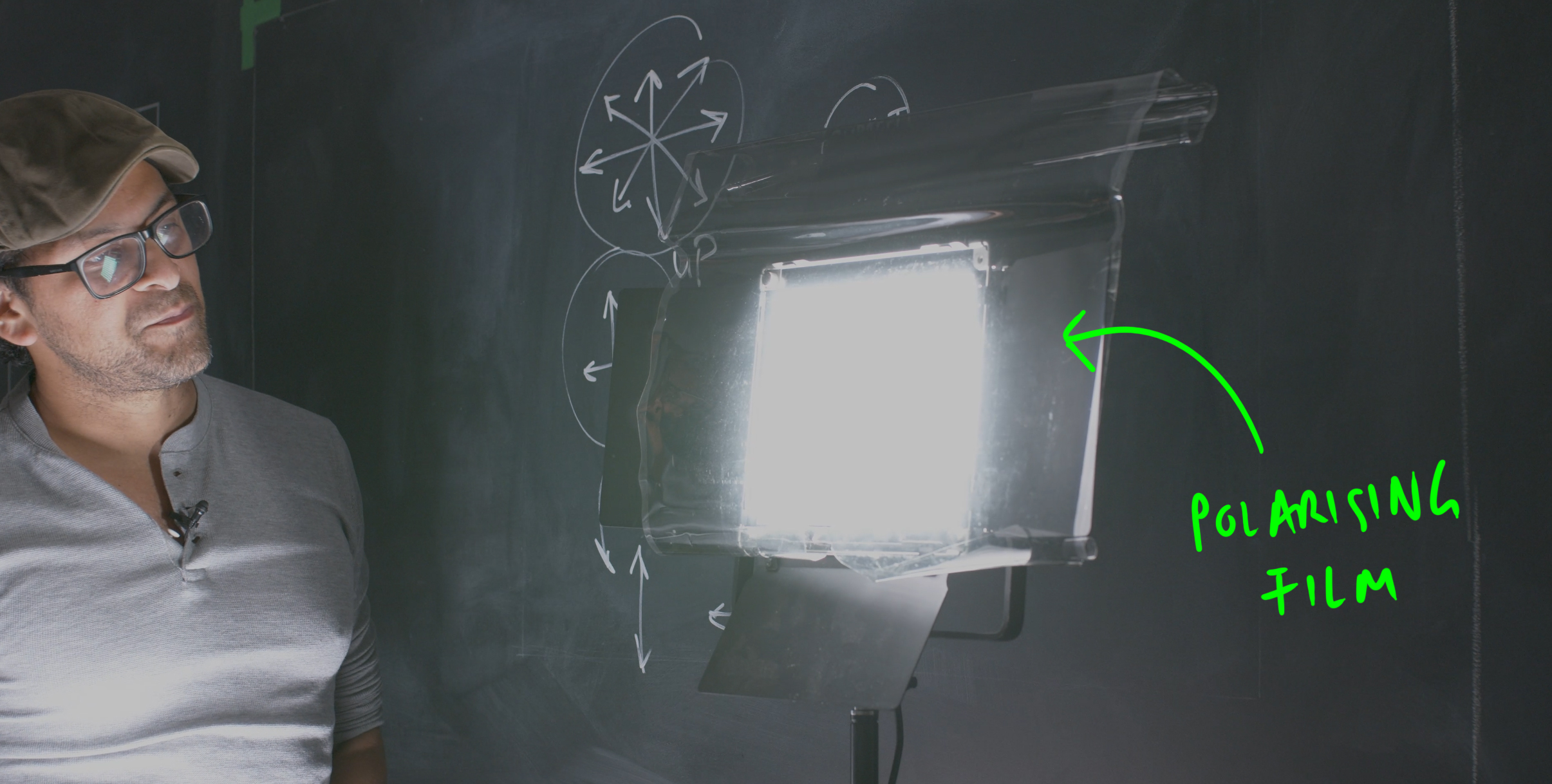
We can transform unpolarised light into polarised light by using a polarising filter that sits in front of the emitting light, or by fitting a circular polarising filter on the lens. The chemical composition of the filter can restrict the vibrations of the electromagnetic wave to a single plane (either vertical or horizontal). By restricting one half of the vibrations, we’ll also be reducing one-half of the intensity of the light, so we’ll need to factor this in when shooting reference. Again, this is where the Macbeth chart comes in, so make sure to shoot it under polarised light.
For example, a 100mm lens has twice (2x) the focal length of a 50mm lens, so it will have a field of view that is 1/4 the size (1/2 x 1/2). 14mm ...
The cross-polarised and polarised images will need to line up perfectly in order to subtract the specular component (which can then be used as visual reference to compare against the specular AOV).
2009327 — The first three chapters present an introduction to the principles of optics and the unique aspects of the infrared region of the wavelength ...
Do note, however, that some sources will emit polarised light, for example, the light from your computer screen will more than likely emit polarised light.
The “minimum focusing distance” lens specification can be confusing. Minimum focusing distance is measured from the subject to the rear focal point of the lens, which is at the image sensor plane in the camera body. The term “working distance” is used to describe the distance between the subject and the front element of the lens.


 Ms.Cici
 8618319014500