
A Journey Through Time: The Different Types of Camera - different types of cameras
Digital interfaceGuitar
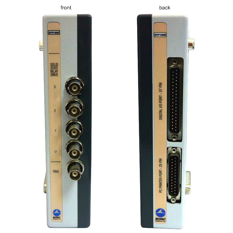
The STP100D is used to safely isolate digital inputs (in the range of 0-3.3 V or 0-5.0 V) and outputs to and from an MP System (MP200, MP200, MP100). The STP100D also includes output to drive solid state relays and incorporates a BNC accessible External Trigger input line. All inputs and outputs associated with the STP100D safely isolate connections to the MP System to 1500 VDC isolation.
Output Drives (for relays)—The STP100D/-C can drive up to four (4) solid state relays directly via MP System Digital I/O lines 0-3. MP System Digital I/O line 4 is used as an enable to activate these drive lines. ON = low (0 V) signal on I/O line 4 OFF = high (5 V) signal on I/O line 4 The output drives (for relays) have 0 to 5 V output voltages and are current limited with 200 ohm resistors. This means that for solid state relay drive requirements, output current will be limited to approximately 20 mA, assuming an optically isolated solid state relay input diode drop of 1.2 V. Nearly all solid state relays can operate with as little as 5 mA of current drive.
The STP100D/-C is designed to work with digital inputs in the range of 0-3.3 V (which is increasingly common with laptop I/O cards and printer ports) or 0-5.0 volts.
Digital interfacedesign
To externally trigger MP Unit acquisition, send a TTL signal to the External Trigger of the STP100D/-C (TRIG). This line connects to the MP Unit External Trigger via optical isolation.
Digital interfacesoftware
Isolated External Trigger Input—The optically isolated external trigger input is TTL compatible. This line is accessible via a BNC female connector (labeled TRIG on the front of the STP100D) and connects to the MP unit External Trigger input via optical isolation, compliant to 1500 VDC. The voltage range for this drive must be 0-5 V (TTL input levels).
Additionally, to use the STP100D/-C external trigger in a manual mode, the input can be pulled low with an external switch connected between the trigger input and ground.
Digital Lines—Use to connect digital signals (TTL compatible) from any mains powered external equipment to an MP System when the system also connects to electrodes attached to humans. All lines on the STP100D are optically isolated to 1500 VDC compliance.
Digital InterfaceAudio
The minimum pulse width to the STP100D/-C trigger input must be 40 µsec or greater; the pulse can be positive going or negative going and the MP System can be set up to accept triggering on either the rising or falling edge of the trigger signal.
To use an MP System line that is normally dedicated to an I/O input (lines 8-15) as an External Trigger drive, use a JUMP100 jumper wire to connect that line directly to External Trigger (EXT T) on the back of the UIM100C.
Start a search by clicking on one or more of the basic body type icons, then narrow your selection by adding search filters below.
Digital interfaceexamples
Use the Digital inputs to stim events tool in AcqKnowledge to automatically score and label digital event marks from the SuperLab presentation. The digital channels are interpreted as a binary number. Each stimulus event placed into the graph has the corresponding number included with its label. This allows further analysis to distinguish between different types of stimulus events for automated event related analysis.
When the STP100D/-C trigger is unused, it is pulled to a high state (+5 V) via an internal 100 kohm resistor. To properly drive this line, connect a standard TTL driver to this port. For non-TTL type drivers, the low voltage applied to a trigger must be between 0 and 0.5 V. The high voltage applied to the trigger must be between 2.5 and 5 V. The maximum recommended source impedance of the driver should not exceed 1 Kohm.


 Ms.Cici
 8618319014500